The ultimate aim at the moment is to liberate all things radio from the confines of the man cave to the arena of fresh air. This needs a different radio (we’re aiming at an Elecraft KX3 but until the Elecraft fairies leave one at the foot of the bed . . .) and a portable antenna.
In the grand schemes of things I’m planning a budget for this project and that needs to include the antenna. The original thought was towards a Buddiepole.
http://www.buddipole.com/ but with a price tag just shy of £400 for the basic kit, before you add all the little extras that you either want or need, that’s a big chunk of cash! So you’re left with the situation of owning a radio but still being confined to the indoors.
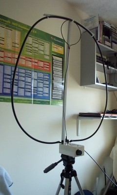
This set me thinking. I’d seen a demonstration of a magnetic loop by Graham (M0CYX) and was impressed with what a 2 foot diameter loop of copper wire could do.
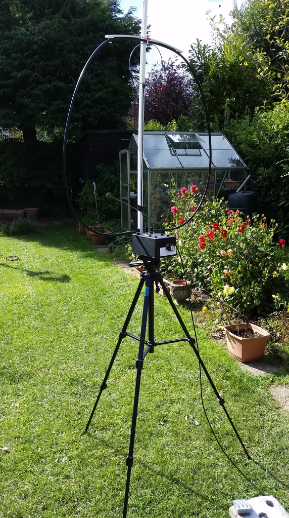
You can see the loop on the back of this rig and the reduction in size to a Buddipole is obvious.
For those of you (you know who you are) who may be scratching your head already at this one, here’s the science part.
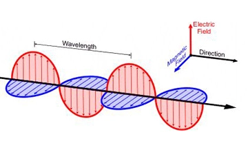
A radio wave is composed of both a magnetic (H) and electrical (E) field. These fields are at 90 degrees to each other and are in phase.
The relationship between the magnitudes of the E and H fields is constant and one cannot exist without the other.
https://en.wikipedia.org/wiki/Radio_wave is worth a read if you want some background.
http://adam.curry.com/enc/20150119092647_article-antenna-mag-loop-2.pdf is another invaluable read on this topic.
The upshot of this is that you can receive the magnetic field as easily as the electrical field with the correct antenna.
Now I was trying to remember what a Wonder Wand Wonder Loop was called and was trawling the internet trying to find the cost (considerably less than a Buddipole by a factor of 4) when I stumbled across a few snaps of homebrew loops which got me thinking. Could I make one of these for cheaper than I could buy one?
My initial though was no, as a lot of the antennas people had made were quite serious engineering jobs utilising copper tubes or aluminium sections. Also, they didn’t seem very portable. You’d either needed a Transit van to move them around or you’d spend a month of Sunday’s bolting the required pieces together. Admittedly each to their own and part of my brief is quick deployment to maximise time on the ground or air as the case may be.
As much as I like building things, spending a fortune on the tools to make something or the raw materials, when you can buy something that does the same thing seems a bit defeatist.
Also in the absence of Elecraft fairies, I’m not spending anything on anything if it can be avoided! And then I stumbled across this.
This is the G4ILO Wonder Loop from http://www.g4ilo.com/wonder-loop.html. Julian’s site is truly inspirational and if I could spend a month just sat reading it from front to back I would.
Now the list of build materials was incredibly short on the electrical front and the fixtures and fittings similar, which meant this could be a runner!
Why am I doing this when I haven’t got a portable rig yet? In the immortal words of Ferris Bueller “Life moves pretty fast” and there’s no point contemplating your navel when other sides of a project can be progressed.
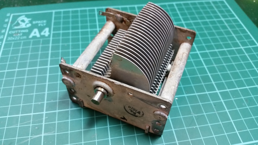
The biggest problem for this build would be finding a suitable capacitor as my eBay and Google search crashed and burned in an instant. It transpires that variable air spaced capacitors are very much a thing of the past. The necessary component can be seen here to the right of the photo.
Annoyingly I had a few of these as a kid when I made a crystal radio, but I can’t for the life think where they went as most of my junk has travelled with me over the years and I’ve still got components I bought with pocket money as a kid in my storage trays and racks.
That wasn’t very encouraging in the slightest and I was just about to consign the idea to the “forget it pile” when I decided to consult the mighty knowledge base of the FPARC Forum.
Light blue touch paper and retire! Talk about champions! In less than 12 hours I had offers of capacitors, reduction drives and lots of advice. All I can say is the inventor/engineer streak must be in most men as I’ve got piles of stuff in cases for the “I’ll need that one day” moment and it looks like the rest of FPARC are the same. Except they’ve actually got useful things. My radio scrap is nil and I need to start bin diving.
To anyone out there reading this, if you’re about to bin anything with a knob or dial on it, especially if it’s old and TV, Hi-Fi or radio related please, please, please can I have first refusal?
A rummage around the back of the garage resulted in a project box, fittings and the like which had been gathering dust. All this within 18 hours of my post on the forum!
OK, 24 hours on and we’re doing even better than yesterday! Courtesy of Mick (M0GWD) we have one reduction drive
Rod (G4SPS) dug out a Johnson 167-152-9 single gang, air dielectric capacitor with a ceramic base, silver contacts and two solder lugs. The part number reveals that it’s 11.6 to 202pf. As the man said in his email “Close enough for government work!”
The only snag with arousing the interest of the assembled mass of FPARC is that it spurns a real ground swell of interest. Not a bad thing BUT next thing you know, there was a suggestion that we ought to hold a magnetic loop contest, so no pressure what so ever to get this thing right!
The all round nice guy Mike Parkin (G0JMI) of Alton Antenna Arrays had offered up another option from an old ATU he had laying around, which appears to be in the 200-300pf range and gave me other options.
Another rummage around the garage had yielded even more bounty in the form of a nut which fits the thread on my camera tripod so I can build a suitable mount, number plate fixing bolt covers, M spec nuts and bolts in assorted sizes, Velcro, uPVC electrical conduit and a few more odds and sods.
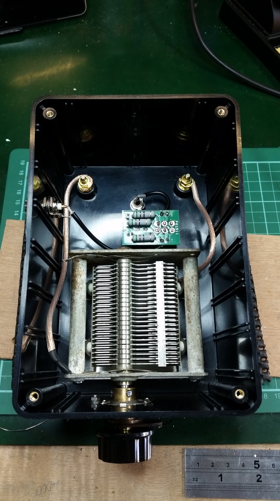
At this rate purchases for this were going to be limited to the N7VE SWR Indicator Kit http://www.qrpkits.com/swrindicator.html , screw terminals, spade connectors and a few off cuts of coax which I hoped to be able to get from Nevada. Annoyingly I would have to buy the indicator kit as I’d no toroids or power resistors lurking in my stash and by the time I’d sourced them and paid postage it would have cost as much as a nice little kit that someone’s already put together.
That said I was thinking about dubbing this project the “Skinflint Loop” or “Scrounger Loop”. Not very catchy though!
That little conundrum was resolved the other weekend when I shot up to Mike’s on my bike to collect the capacitor. It was one of the hottest weekends so far and foolishly I cracked open the visor on my helmet to let some air in only to be rewarded by a wasp ducking in at 30mph plus and peppering my face with wasp venom in disgust at the Man v Wasp encounter. When I took my lid off when I got home my face resembled a chipmunk that had been given a free reign in the peanut factory! Just what was needed. That said the naming problem was overcome. The M0XXF ‘Wasp Loop’ was born.
Two weeks on and things hadn’t progressed very far due to a combination of things going bang elsewhere that needed fixing, the inconvenience of having to go to work and people on eBay listing item locations as “within the UK” only to find they were actually shipping from Guangdong Province, China. Not sure how that sits in the grand scheme of things but it generally inconveniences project progression!
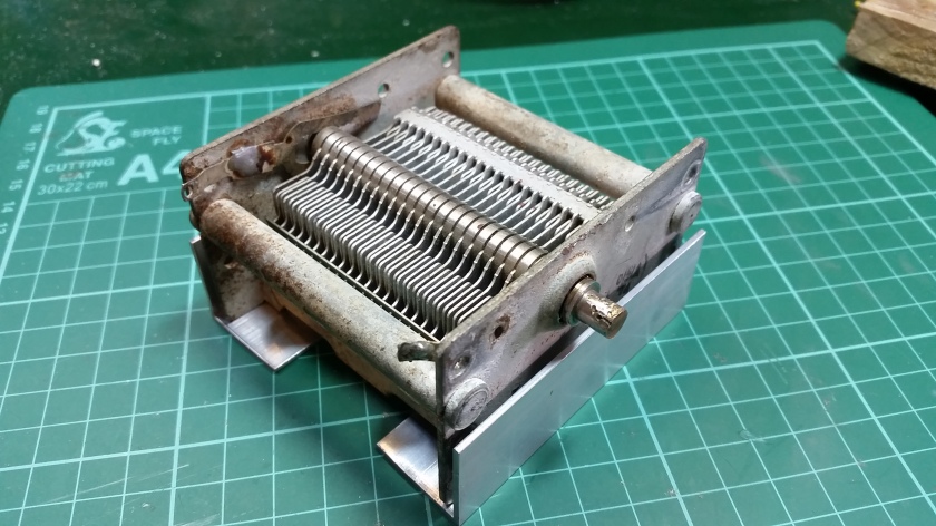
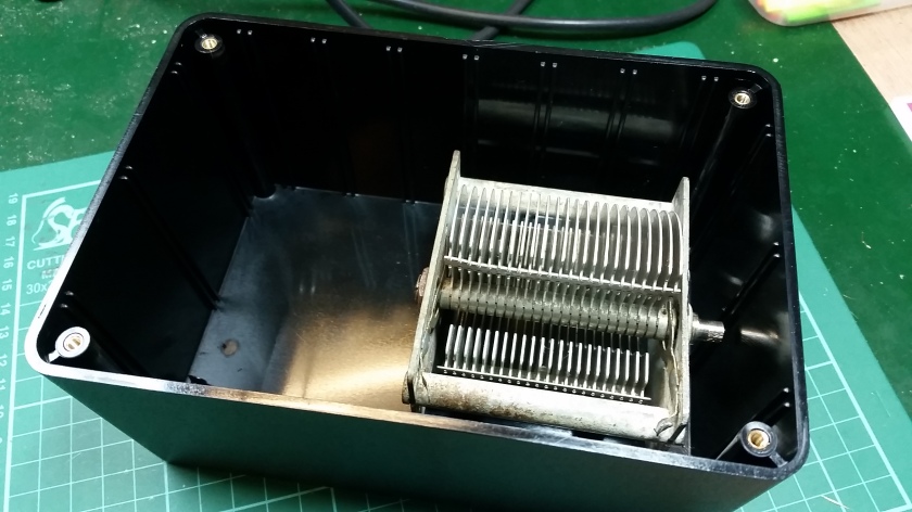
The first stage was to mount the 350pF capacitor. Now this thing is a big old beast and is considerably heavier than the other bits and bobs I had accrued. The solution was to fashion a bracket from aluminium to support the mass robustly rather than hanging it on a few M3 screws and small angle brackets. As the case is inverted on completion, the whole weight would be hanging on very small screws with the real possibility that it could pull them through the drilled holes in the case and causing the tuning knob to catch on the case. The way to avoid this was to use anything larger than the small M3 screws I had in abundance.
The larger size of the capacitor meant I needed a taller box than the one I had to hand. When the central spindle is rotated the air separated plates stand proud of the chassis making this thing bigger than anticipated.
With a bit of work the mounting brackets started to take shape
With some gentle filing the existing holes in the chassis of the capacitor will take an M4 machine bolt. This thing hails from the days of imperial measurements so nothing I’ve got fits and I’m not chasing down half a dozen imperial sized bolts.
You get the general idea of how this will work. Top tip for this project is protect the bottom of the project box. This is going to be your sunny side up when done and with it sat on a workbench in amongst metal swarf will ruin the finish. Masking tape was used to cover it up at an early stage.
The idea of using the larger fixing got me thinking. The G4ILO article warns of the need to insulate the capacitor mounting screws where they protrude through the case and uses number plate fixing covers. Why not avoid the possibility of giving yourself an unexpected surprise with a stray kilovolt of electricity by using plastic bolts to mount the capacitor to the case? eBay came up trumps with nylon machine bolts.

The next snag to overcome was some form of dial or indicator. The problem with a reduction drive is the gearing ratio means that rotations of the knob don’t reflect the degree of movement on the device the other side of the gear box. With a sealed unit there’s a need for a pointer so you know where the capacitor actually is otherwise it could all become a bit frustrating despite the more intricate movement which results.
An unfortunate cock up with eBay (reliance on technology to do your bidding, literally can be fraught with mishap!) meant I waited longer than necessary to get my hands on one of these
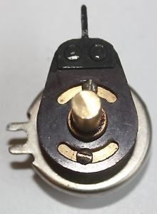
It’s another type of reduction drive but has a nice metal pointer on it which means you can track what you’re doing and can mark the necessary frequencies for the antenna.
A few stages on and we’ve got the capacitor sitting nicely on it’s mounting bracket, the reduction drive hooked up and a few case holes drilled. There’s a temptation to do a blow by blow photo log of this build but that would get a bit boring, so we’ll move on a bit. The thing is this has taken a good six weeks plus to achieve what, if you’ve got the time, can be completed in an afternoon! That said, the time scale has made this even more rewarding.
This is the completed unit minus a few stickers, but you get the idea.
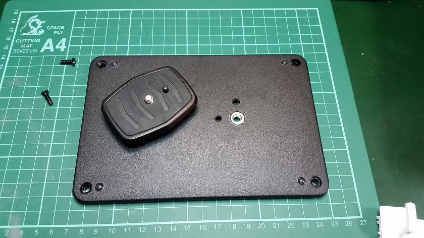
A real fiddly bit was making a mount so that the whole antenna could be tripod mounted to reduce ground effect. Two snapped needle files later I’d got a suitable hole in the case to fix the correct sized bolt to attach to the shoe of my tripod.
And there we have it, one unit at beta stage ready for testing. I used the same mini trunking support idea as the G4LIO project and found that where my box was slightly tapered in profile the mast leant forward making things unstable. A uPVC window packer was used to space the trunking at the top of case to restore the vertical orientation.
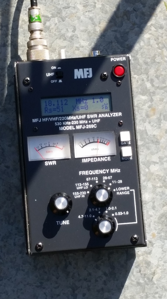
The best bit of this project was being able to let antenna expert Mike G0JMI give it the once over for me, only to find that without any modification whatsoever it worked. Not just worked, but was an absolute killer on 20 and 17 meters. Operation requires the unit to run through an ATU, but the antenna analyser images below show the great SWR readings.
Successful QSO’s were made using 10W with LY3X in Lithuania on 17M USB reporting 57 and E7SE in Yugoslavia reporting 58; using 20W R90IARU in the Ural Mountains on 40M and on 20M OM3TWM reporting 57.
Points to note are that when tuning the unit hand capacitance really does effect the results, but by tuning slightly under, when your hand is removed the ATU can fine tune quite nicely. Also the feeder really does effect the unit. The capacitance of the cable noticeably effects the unit so I’ve made a dedicated cable to use with the antenna.
I’m really pleased with the results of this project as it hasn’t been the smoothest of builds simply due to interruption but I’ve now got the means for portable work. All I need as a radio to plug it into!


