Rather than loads of posts, this blog is going to be my notebook for the QSB-01 in a rolling style. Also, rather than bore you to death with a blow by blow account it is simply going to be the necessary photo or answers requested by Yoda (Chuck Adams K7QO) at the conclusion of each phase of the build, along with a few others where relevant.
For it to all make sense have the necessary QSB-01 web pages one and two to hand.
____________________________________________
Phase 9 – LPF Section
Commenced 12/04/16 Completed 26/04/16
It’s taken two weeks to insert 5 components! That’s what happens when servers go wrong!
Phase 9 assembly work

Phase 9 testing

Video file – Phase 9 testing of completed receiver section
https://www.dropbox.com/s/zrnvkta3eyp0bip/20160426_162406.mp4?dl=0
Unfortunately, on the day the band was closed with absolutely no QSO’s to test the receiver against which is a real shame.
Phase 9 completed


____________________________________________
Phase 8 – TR/BPF Section
Commenced 12/04/16 Completed 12/04/16
Phase 8 assembly work

Phase 8 testing

Phase 8 completed


____________________________________________
Phase 7 – Advanced Testing Addendum
The display unit as it stands is pretty good but would be vastly improved by calibrating it, as the supplier comments that it shows 100Hz error when checked against a 10MHz reference standard. There is a trimpot on the board which allows calibration but I don’t own a DDS Frequency Standard. Remember the old “How to Build an Atomic Clock” post? Yep, that rubidium standard would really come in handy now!
Now without anything like that readily available, in a flash of inspiration/desperation I remembered my Elecraft XG2 Receiver Test Oscillator that I had paid a stupid amount of money for (129€’s to be precise!) when I was setting up my SoftRock Ensemble.

So at 4.3€ or £3.34 per component it seemed silly not to see if it would do the trick as it provides 50uV and 1uV signals for 80m, 40m and 20m.
In short, it didn’t, which is a pain, but thankfully I’ve found someone with a 10Mhz frequency generator who will be able to loan me 5 minutes of their time at some point to calibrate things.
____________________________________________
Phase 7 – Impedance Matching Transformer T4 and Band Pass Filter
Commenced 06/04/16 Completed 06/04/16
Phase 7 assembly work

T4 torroid transformer 4T:28T


Phase 7 Testing


Audio file – power up, no wire, 15cm wire @ L3, 15cm wire @ L3 adjustment showing two peak positions
https://www.dropbox.com/s/lqyt3czbj8ffg9x/Phase%207%20testing.m4a?dl=0
Phase 7 Advanced Testing
This required a separate build of a digital display unit. I went for the one plugged by Chuck at http://www.qrpguys.com/


Having set my mind on a final enclosure and so forth building the display threw a spanner in the works as it’s a really cool addition. As such I built it so it could be enclosure mounted (trimmer pot and push button mounted on the rear rather than front for easy access once mounted).

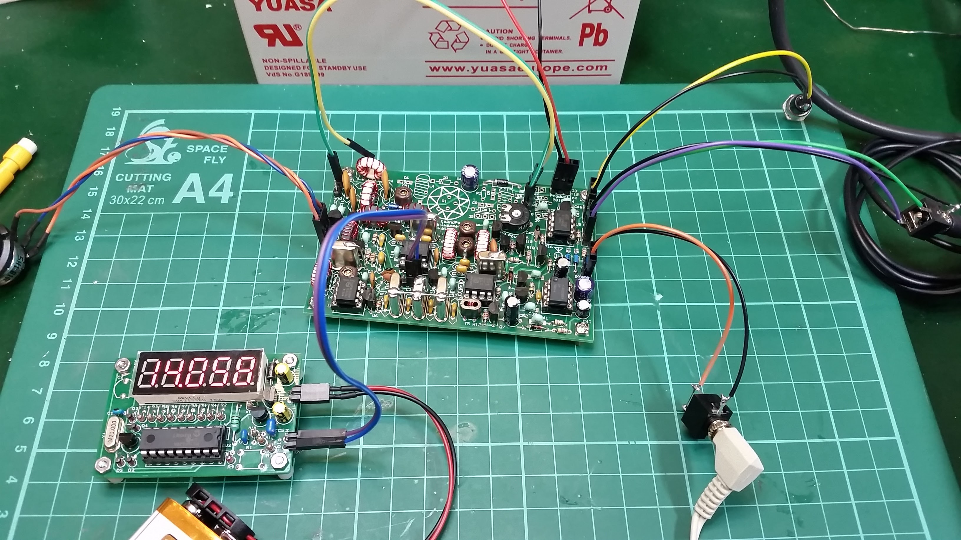
Once built the display is attached to the header at J7. I added a tuning pot at J1 to allow testing

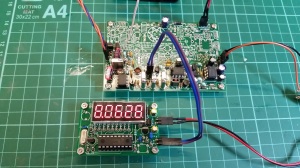
My camera struggles under all the lighting on my bench to show the display with the clarity it provides in reality

Video file – Phase 7 advanced testing with the display attached to the VXO
https://www.dropbox.com/s/qad5p4q5fz23zu9/20160407_190949.mp4?dl=0
Now the astute amongst you would have noticed that the display is saying 8.0628MHz. For 20M you’d be expecting something around 14MHz, which you get from mixing the VFO frequency with the IF (intermediate frequency) of the receiver. The display is taking its single input from the VFO, which is variable. The clever bit comes in that the display can be set to add or subtract the IF. In short you plumb the display to the IF at pin 7 of U5, power it up, hit the button on the unit and it saves it to memory. Now, when it is reattached to J1 it takes the value from memory and adds it to the input value giving you your desired frequency. It really is that simple!
Phase 7 Completed

____________________________________________
Phase 6 – Variable Crystal Oscillator (VXO) Section Testing
Commenced 06/04/16 Completed 06/04/16
J1 Voltage = 9.94V
Audio file – 15cm wire placed at pins 1 and 2 of U4
https://www.dropbox.com/s/iger33dzx3jgvrs/Phase%206%20testing.m4a?dl=0


____________________________________________
Phase 5 – Variable Crystal Oscillator (VXO) Section
Commenced 05/04/16 Completed 06/04/16
Phase 5 assembly work


Phase 5 Completed


____________________________________________
Phase 4 – IF Crystal Filter
Commenced 02/04/16 Completed 05/04/16
Phase 4 assembly work


Phase 4 Testing
15cm wire placed at pins 1 and 2 of U4
https://www.dropbox.com/s/0qdegbd5tezkn53/Phase%204%20test.m4a?dl=0
Phase 4 Completed

____________________________________________
Phase 3 – Audio Detector Mixer (BFO) Installation
Commenced 27/03/16 Completed 29/03/16
Phase 3 assembly work


Crystal testing

Not all crystals are equal! Two showed fluctuation between 5.9993-5.9994MHz with some stability after running and warming up(?)
Winding T5 binocular toroid
Hardly blog worthy other than the instructions at Kitsandparts.com aren’t very clear and never having wound one of these before it was worth noting for future reference.

In one hole and out the other constitutes ONE turn. As such if TWO turns are completed there will be TWO “wraps” of wire visible at one end of the toroid and ONE at the opposite end


Resource
Click to access calmont-eng-wire-gauge.pdf
The magnet wire in the kit isn’t marked and is supplied all in one bag! Now bearing in mind the difference between some of the gauges is fractions of millimeters a fair amount of time was spent checking and double checking with a set of digital calipers and then clearly labelling each to prevent any cock up!
Phase 3 Testing
On power up hiss heard BUT no difference in noise heard when 15cm wire touched on upper pad C32!
Phase 3 Advanced Testing
When a crystal oscillator with a 6MHz crystal is placed next to the 1Watter at this point in the build a distinct oscillating tone is heard.
The lack of any tone change being heard at basic testing was nagging so I sought advice from Chuck on this one.
His advice was to place the crystal oscillator away from the radio and then place the 15cm wire on the non grounded pad of C32.
With the oscillator 10″ from the board, with no wire nothing can be heard. With the wire touched against the pad the oscillator can be heard as clearly as when they are next to each other. Chuck’s advice, if you can hear that all is good! The suggestion is there’s insufficient electrical noise within the house to up the background noise, hence the lack of response at basic testing.

Phase 3 complete


____________________________________________
Phase 2 – Commenced 27/03/16 Completed 27/03/16
Phase 2 Part 1 assembly work

Phase 2 Part 1 assembly completed

Reverse side of PCB

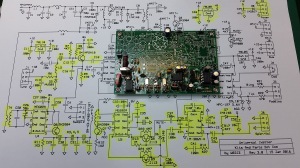
Highlighted section of schematic reflects completed build on PCB
Phase 2 Part 1 Testing – A/C hum test at C37 & C38
https://www.dropbox.com/s/omeo118p3vv7cgf/C37-C38%20AC%20hum.m4a?dl=0
Phase 2 Part 2 assembly work


Phase 2 Part 2 Testing – A/C hum test at U5 pins 4 & 5
https://www.dropbox.com/s/w1sx0pslzv8qh4q/U5%20pin%204%20%26%205%20AC%20hum.m4a?dl=0
Phase 2 Part 2 Complete


____________________________________________
Phase 1 – Commenced 27/03/16 Completed 27/03/16
Homework Completed
Workbench
Ordered & Delivered 1Watter 20m kit – S/N 607
Phase 1 Assembly work

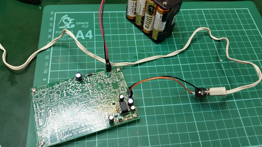
Phase 1 assembly completed – Jumper power connection to PCB & completed power supply section

Reverse side of PCB showing solder connections and stand off spacer

Highlighted section of schematic reflects completed build on PCB
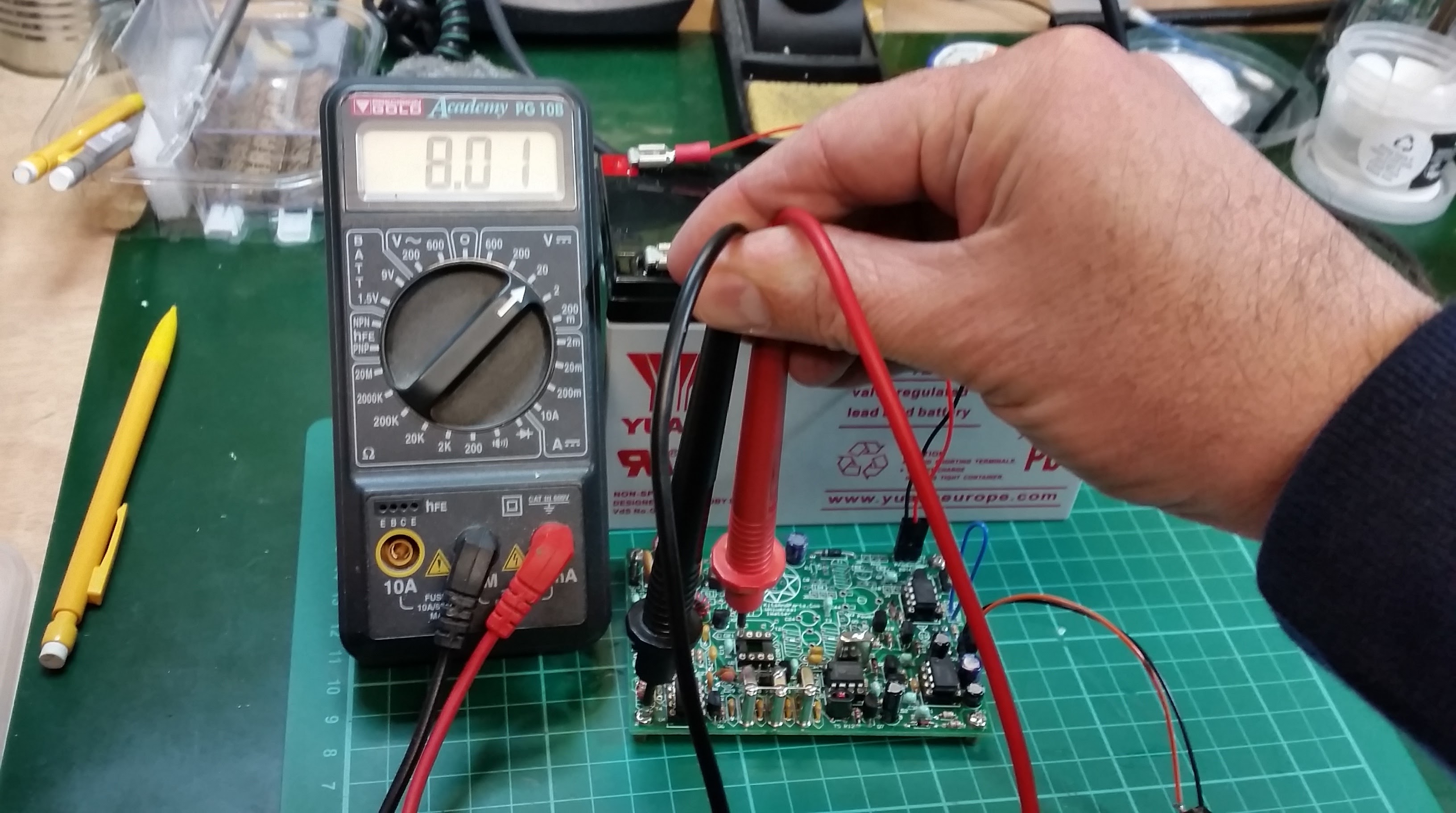
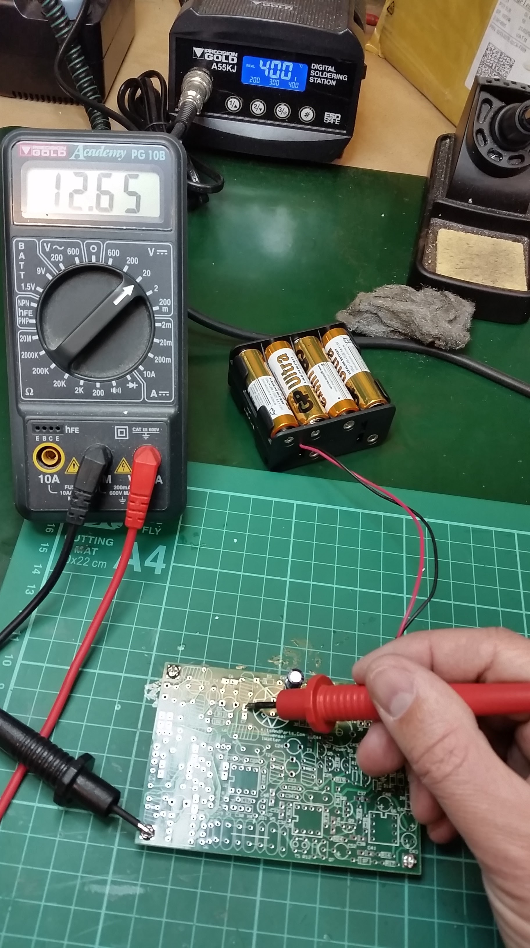
Phase 1 Testing

Voltage test at C7 top pad – 12.65V, battery voltage – 12.72V

Reversed polarity voltage test

Further voltage checks at U6-6
Battery = 12.72V, Voltage at C7 = 12.65V, Voltage at U6-6 = 12.66V
Enclosure considerations

1/ BUD Industries aluminium enclosure available from Mouser – commercial option

2/ QRPbuilders double sided PCB enclosure for 1 Watter – homebrew


