QSB-01 (qrp-tech synchronous buildathon) #7 – Final Details – Custom Case Decals

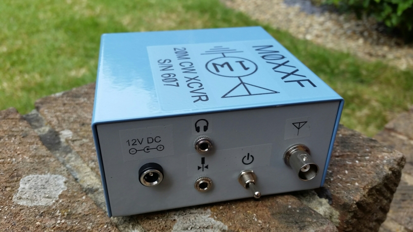
Having spent a lot of time building my 1 Watter I wanted it to look half decent in its enclosure and had a good look around at my options for labeling up the case with something funky to do it justice.
As big a fan of the old Dymo labeller as I am, I’ve never been 100% happy with the finish I’ve achieved when I’ve used them. Although functional they’ll never win any prizes.

A bit of research unearthed the idea of custom decal printing. This is something I’d never even considered. Bearing in mind the number of Airfix models I built as a kid, it never crossed my mind that things in that department had evolved with the whole IT concept of “print your own”.

My favoured option would have been to use the media which you run through a laser printer to give the most crisp output, but not owning one and in a similar vane to the Dremel bench saw project, I wasn’t about to go and buy one for a single job, so left it in the hands of my Epson Stylus Photo R360 to see what it would do with the ink jet media.

20160529_093106

Mr Decal Paper (real name not me being flippant) on eBay supplied the decal sheets and the instructions which made life a bit easier. You need to seal your printed sheet with spray varnish to prevent the immersion in water stage from causing everything to run off the page. A trip around the art section of The Range provided a solvent based product rather than a water based one which would have defeated the whole object.

I designed the decals in a combination of PaintShop Pro, MS Paint and MS Word. The dry run on plain paper was spot on but the actual print on the decal paper was less than polished. I’ve had this before with ink jet inks not wishing to play ball with media other than the massively overpriced product from the manufacturer. As Epson don’t produce a decal paper I’ve got to live with it.

Now despite my anticipation of thunder storms on a Bank Holiday weekend, the weather proved me wrong and in effect was perfect for turning the garden washing line into an impromptu spray bay.

20160529_153604.jpg

My three coats took seconds to dry in the heat but I still gave it ample drying time between applications to prevent any mishaps.

The next morning brought judgement day along with an assessment of my ability to accurately cut things out with a slide cutter and pair of scissors.
Like the Airfix kits of the 70’s a quick soak in water releases the decal from its backing sheet allowing them to be applied.

20160530_093828.jpg
20160530_101238.jpg

20160530_101214.jpg

Not bad for a first attempt! The instructions suggest a drying time of 24 hours or a spell in a low temperature oven to harden the decals dependent on the surface they’re applied to. I’m not sure my 1Watter would see the funny side of that!

Mountain Topper MTR-5B

Faced with the choice of having to spend Saturday evening watching Britain’s Got Talent (a contradiction in terms if ever there was one) or push pins into my eyes, I chose the third option and built another radio!

Now this was a little forward as I still haven’t put the finishing touches to my 1Watter but given the circumstances I think I’m allowed a little latitude.

When I was hunting around on the internet for ideas of what was small, portable and a potential project I stumbled across several reviews for the Mountain Topper in its earlier guise the MTR3B

379640809

Rarer than rocking horse droppings on this side of the atlantic these things get great reviews from people who like yomping up mountains for a bit of SOTA action.

Like everything, these radios evolve and the latest offering is the MTR5B and again even rarer!

379503153

When I first saw this I was making noises like the little green aliens out of Toy Story and filed the idea in the back of my brain along with plans for global domination, owning an Aston Martin and having Rihanna’s number on speed dial.

That is until Kanga Products emailed me, offering me the opportunity to own one of these as I’d expressed an interest while perusing their website. It took nano seconds to think that through.

I had to wait a week or two for it to arrive and to be honest there were degrees of reservation as to what was going to be in the box as my original research was on the complete kit which involved a hell of a lot of SMD work.

I like a challenge but there’s a point when you have to admit your limitations and this may have been it. The box yielded this

20160528_191909

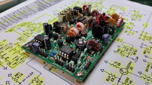
That’s a bit more like it! So half an hour later we have this

20160528_203037

20160528_203050

20160528_203110

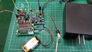
It really is that small and all it wants for optimal performance is a 9V battery.

Now the MTR5B is a five band transceiver so there’s lots of potential out there as you’ve got 40-15 meters to play with.

This evening there’s plenty of activity on the air so the smoke test went something like this

https://www.dropbox.com/s/hhbyqutasaxirr5/20160528_204332.mp4?dl=0

The only word for it is “Awesome”

I wanted a portable solution for sitting in the sun with and it doesn’t get any more portable than this!

You watch the Bank Holiday weekend descend into a wash out just to spite me!

QSB-01 (qrp-tech synchronous buildathon) #6 – And the fat lady sings!

So after several weeks / months of interrupted building we’re there!

Now admittedly it’s not in the enclosure I wanted to build, which was this

Screenshot 2016-03-09 14.41.42

but you can’t have everything! A PCB enclosure requires the ability to cut reasonably straight lines in your medium with repeatable accuracy. To do this I was planning on using a Dremel mounted horizontally in a 3D printed purpose made frame which converts the drill into a bench saw. Unfortunately part way through printing, my good chum Mat’s printer decided it had had enough and requires a bit of rebuild work and maintenance to get it back working. As such I don’t have a completed table/platform for the Dremel holder.

That said, every cloud has a silver lining. A Dremel would have set me back seventy odd quid, plus the additional hardware for the frame. The cheaper solution was an LMB/Heeger CR-442 painted enclosure from Mouser. Even with the duty charges and shipping I was out for less than a third of the cost of the Dremel saw table project and probably got to keep a few more fingertips into the bargain. If I build another 1Watter (and I will) I’ll look to box it in the bespoke built enclosure if the printer is back working.

So (drum roll please), here it is!

20160520_174239

20160520_174149

20160520_174029

20160520_174059

If you want to save yourself several hours with a set of calipers and some graph paper trying to work out what will fit where (and it is tighter than the proverbial in there!), here’s a copy of my drilling template. Print it at full size A4 and you’re good to go.

scan-160521-0001

OK, the enclosure needs a bit of artwork to liven it up and to make sense of the controls and connections (separate post for that bit) but the soldering iron is officially cold!

Now on first reveal to those at home, I got a “Ah, isn’t it cute!”

Not what I was expecting! I was trying to build the QRP equivalent of Dr. Heinz Doofenshmirtz’s “Inator’s Inator” here (you have to watch Phineas and Ferb to truly get that one I’m afraid) so people cooing over it is not what your kick-ass QRP radio wants to here. That said it’s a nifty little package.

The best part of a day was spent tinkering with the final setup and alignment as per Chuck’s YouTube video #9.

20160521_135904

This one’s a must. I was really surprised to discover how serious the relationship between the adjustment of C24 and C25 was when aligning the transmitter. I was wondering why I was seeing absolutely nothing on my power meter when I was keying until, Boom! The power was rocketing past 1W in a hurry. All good stuff.

As part of the build up to this project I invested in a frequency counter from eBay. The supplied item turns out to be a PLJ-1601-C which comes with absolutely nothing. Google provides you with a manual in one flavour – Chinese. So, with a little bit of effort here’s an English language version I made using Google Translate.

PLJ-1601-C english translation

PLJ_1601A – chinese language

It’s free and comes with no warranty, acceptance of liability etc etc etc. Just be grateful someone made your life easier for you rather than having to attend night school to learn Cantonese!

** Addendum 29/07/16 – Many thanks to Trevor Newstead who has noticed that for some bizarre reason all of the images have disappeared from my english translation version. I will look to redo the document at a later date but in the short term the original Chinese language version has been added for reference. If you look at the two side by side you can see what’s what. Sorry! it’s on the todo list

With the frequency counter attached to the antenna and everything on a dummy load I get a tuning range of 14.055.86 to 14.060.49 MHz.

20160521_142824

Unfortunately I still can’t get the hang of my Homebrew oscilloscope to get anything sensible out of the frequency analyser to check the spectral purity during transmission, so that’s a job for another day. That said I have managed to get my DS203 to do something useful. Here we’ve got a nice sine wave on keyup!

20160521_160438

The final stage is to design some case graphics, check the output for harmonics and sort out a throw up antenna so I can play outdoors in the sunshine. There’s no point in building a portable rig and sitting indoors when the sun is shining outside is there?

QSB-01 (qrp-tech synchronous buildathon) #5 – transmitter build updated @ 21/05/16

Phase 15 – Final RF Power Amplifier Stage

Commenced 02/05/16  Completed 02/05/16

Phase 15 completed

Completed build requiring fitting in an enclosure, setup and alignment

20160502_152641

20160502_152622

20160502_152726

20160502_152708

20160502_152657

20160502_152607

____________________________________________

Phase 14 – Third Driver Stage

Commenced 02/05/16  Completed 02/05/16

Phase 14 testing

20160502_144218

Audio file – Phase 14 testing

https://www.dropbox.com/s/r5u4lidvjgynpmy/Phase%2014%20testing.m4a?dl=0

Phase 14 completed

20160502_144834

____________________________________________

Phase 13 – Second Driver Stage

Commenced 02/05/16  Completed 02/05/16

Phase 13 assembly work

20160502_133506

Phase 13 testing

20160502_133307

Audio files Phase 13 testing

https://www.dropbox.com/s/raawuy29mk96134/Phase%2013%20testing%20a.m4a?dl=0

https://www.dropbox.com/s/jlitjs3nqmkjdjm/Phase%2013%20testing%20b.m4a?dl=0

Phase 13 completed

20160502_133324

____________________________________________

Phase 12 – Transmit Band Pass Filter (BPF) & First Driver Stage

Commenced 28/04/16  Completed 02/05/16

Phase 12 assembly work

20160502_122651

Phase 12 testing

20160502_122641

Audio file – Phase 12 testing

https://www.dropbox.com/s/bhfaolycjbh8f03/Phase%2012%20testing.m4a?dl=0

Phase 12 completed

20160502_122925

20160502_122848

____________________________________________

Phase 11 – First Transmit Mixer

Commenced 27/04/16  Completed 28/04/16

Phase 11 assembly work

20160427_182805

Phase 11 testing

20160428_165908

Video file – test operation of the first mixer stage

https://www.dropbox.com/s/sx06ujqmwz6q8kq/20160428_170056.mp4?dl=0

This testing stage is clever in that it is using the receiver to test the transmitter in a feedback loop where the output of the first transmit mixer is fed into the antenna input. This comes with a caveat of don’t do this under any other circumstances else risk destroying your creation! In the above video the audio output of the keyer has been switched off by entering the command mode and disabling it. As such the tones which are heard are those being produced by the transmitter. The technique negates the need for any test equipment which is a bonus for those without those resources to hand.

Phase 11 completed

20160428_172853

I’ve corrected the display unit now by adding the IF frequency to the display’s memory function. Now it adds 6MHz to its received input giving a more accurate and usable reading

____________________________________________

Phase 10 – Keyer & Keying Circuit

Commenced 26/04/16  Completed 27/04/16

Phase 10 assembly work

20160426_184917

Phase 10 testing

20160427_165841

Video file – Keyer Circuit test

https://www.dropbox.com/s/mtlbdey5fdmjr1u/20160427_172713.mp4?dl=0

20160427_175401

20160427_175428

Phase 10 completed

20160427_172937

20160427_172928

20160427_173027

1Watter YouTube video resources

The following videos were produced by Chuck Adams K7QO and although they don’t follow the step by step guide as per his website they are a very useful resource especially phase 9 (final alignment and testing) and phase 10 (introduction to the 1Watter keyer)

Phase 1

Phase 2

Phase 3

Phase 4

Phase 5

Phase 6

Phase 7

Phase 8

Phase 9 – Testing and alignment of completed 1Watter

Phase 10 – 1Watter keyer

Aluminium enclosure construction